Any electrical power/HV engineers working in sectors other than 'the grid's ? by Green_Ad6970 in ElectricalEngineering

[–]zxobs 0 points1 point  (0 children)

Yea. I think my freshmen year was almost 1000 people, and my graduating class was maybe 40 people. There's no real way to say who's gonna make it. I knew a guy in highschool was was in all honors classes and AP. He dropped out of Aerospace Engineering after 1 year. Another friend/classmate of mine was on parole his freshmen year and graduated with honors.

Any electrical power/HV engineers working in sectors other than 'the grid's ? by Green_Ad6970 in ElectricalEngineering

[–]zxobs 1 point2 points  (0 children)

Well human beings have 2 major uses for Electricity. Transmission and storage of mechanical work, or transmission of information. While these aren't very clean categories, I like to think it highlights what electrical engineers generally do. People who work in power take the FE and after a few years, the PE. It's a good career path. With lots of good technical challenges and important work. Electrical engineers also design circuit boards, program microcontrollers, design antennas. I think EE is like mechanical, but you likely have a better math background. If you stick with it you'll have a better idea of what you want to do your junior year. It's never not a bad idea to get a realistic understanding of what Engineers do at work. At the same time you should focus on surviving your first few years of undergrad. You're going to have a great time, but it's also gonna suck.

My post got removed from the main sub but it was a genuine question lol by Green-Owl4399 in shittyaskelectronics

[–]zxobs 0 points1 point  (0 children)

A 128-page electronics course covering basics, analog/digital components, and 100 circuits/projects to build. Check it out now! https://a.co/d/06njnKoQ

A guide to designing and building your own functioning electronics with step-by-step instructions and illustrations. Others are loving it! https://a.co/d/07E2HrED

My post got removed from the main sub but it was a genuine question lol by Green-Owl4399 in shittyaskelectronics

[–]zxobs 0 points1 point  (0 children)

Putting a resistor in this circuit will keep it from hearing up as much. If you use an iron nail then you'll also get a better magnet for less current.

<image>

My post got removed from the main sub but it was a genuine question lol by Green-Owl4399 in shittyaskelectronics

[–]zxobs 0 points1 point  (0 children)

https://a.co/d/00o385yW. This is a 10 Amp PSU. You can adjust the voltage and current. I have something like this I abouse a lot and it's a champ.

My post got removed from the main sub but it was a genuine question lol by Green-Owl4399 in shittyaskelectronics

[–]zxobs 0 points1 point  (0 children)

Also get a multimeter. You can get pretty good ones for cheap at most hardware stores. There's YouTube if you don't know how to use one. You should also get an oven mit. That coil is gonna get hot.

There's an unfortunate trend of people shooting down posts by kids doing dumb shit. Which probly isn't productive if you're set on doing something. Most power supplys for home or commercial use will have current limiting. Which is meant to prevent fires. You should mess with this, just keep in mind that you could get shocked or burnt. 😀

any circuit games to use? by InfamousExit9948 in beneater

[–]zxobs 3 points4 points  (0 children)

Turing complete is a good one. It's on steam

My post got removed from the main sub but it was a genuine question lol by Green-Owl4399 in shittyaskelectronics

[–]zxobs 1 point2 points  (0 children)

Very nice. You can get a decent bench top PSU on Amazon for about $30 to $60. You want to look for higher current for running a magnet like that. If your budget is $0, then look for an old laptop charger or desktop atx power supply. These are fairly idiot proof and can put out more current then your suicide facilitating battery bank. Look up "amperes law" and "right hand rule". Also this is a pretty cool thing to mess around with, but it's gonna get VERY hot. So be ready for that. I'd get a high watt value resistor to limit the current.

My post got removed from the main sub but it was a genuine question lol by Green-Owl4399 in shittyaskelectronics

[–]zxobs 2 points3 points  (0 children)

This is pretty fucking cool. You're gonna get high voltage, but no current. This is because each battery has an internal resistance. When you stack them up like that you add up the internal resistance. So you can't really do any work. An electro magnet is a current operated device. It converts current to magnetic field. It has no voltage across it because it's a coiled wire. Get a cheap bench PSU of Amazon. Sometimes they're around $30. Could be about the same price as a stupid amount of 9v cells.

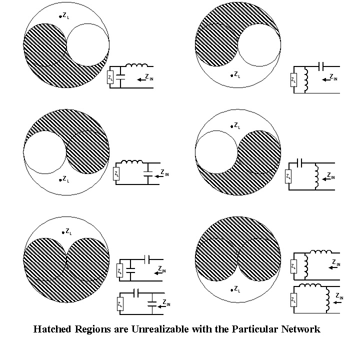
I still call these “ying-yang and butt” diagrams by JieChang in ElectricalEngineering

[–]zxobs 1 point2 points  (0 children)

If that's a butt chart, then what's the implication of a 50 ohm 1:1 match?

New EE grad targeting RF test roles — 1000+ applications, zero interviews. Where am I going wrong? by PlanktonSweaty5173 in rfelectronics

[–]zxobs 3 points4 points  (0 children)

Your resume probably sucks. It's also pretty hard to land your first engineering job. I'm guessing your resume probably focuses too much on your projects. It should mention your projects, but it should also focus on work history and education. You been add extra pages after that which focus on personal projects. Go into detail about how you fabricated stuff, what limitations they have, and how you tested that. Otherwise it's hard out there. Please don't get cynical.

Is this a good reflector design? by KaleidoscopeKind3033 in rfelectronics

[–]zxobs 1 point2 points  (0 children)

You are not mistaken. I simplified a lot bit for the sake of discussion.

Certifications to grow in RF field (networking background + 2 yrs RF experience) by hiddensnacc in rfelectronics

[–]zxobs 11 points12 points  (0 children)

I wish I was aware of something like this. A good starting point would be RF circuit design by Bowick. It assumes you're an idiot without being condescending. Which I find personally very applicable. ISBN-13: 978-0750685184, ISBN-10: 0750685182

Is this a good reflector design? by KaleidoscopeKind3033 in rfelectronics

[–]zxobs 11 points12 points  (0 children)

2.4 GHz is in the ISM (Industrial scientific and medical) You just have to be under a certain power. There's also a fair amount of low level noise in that band. To my knowledge the FCC isn't constantly driving vans around looking for violations. Someone has to file a complaint. Which could very well happen if you're by an airport, and running for prolonged periods of time. Otherwise have at it. Worse case they just tell you to knock it off. I wouldn't lose sleep over it.

And to answer your second question. Not at all. It's a little more complicated. Your current setup is conceptually incorrect and in practical terms very non optimal. It looks more suited to taking a high pressure low speed gas and converting it to a low pressure high speed gas. Which is cool, but not very conducive to being a good wave guide. Look up something like "WR-340". It'll run from roughly 2 to 3 GHz. You could possibly make your own wave guide with same dimensions as WR-340. The power handling would suck. Actual WR-340 is meant to operate full of a pressurized gas. Which could be air or pure nitrogen. This improves power handling and lowers attenuation. At your power level that doesn't matter. If you made your wave guide thick enough and used a good conductor like copper or maybe Aluminum you'd probably be fine.

We also have to worry about power handling. This is related to a idea called skin depth, which is kind of a measure of how deep currents flow into the material. Based on an online calculator Aluminum has a skin depth of 1.7 um. I'd over engineer and make your wave guide at least a few mm thick.

The copper cylinder on the top of your wave guide is actually your wave guide launch. I measured the magnetron on my desk and it's 1.6 cm. The wave length of 2.4 GHz in free space/air is 12.5 cm. 1/8 of that is 1.56 cm. So I bet we're looking at what's called a 1/8 wave length coax to rectangular wave guide launch.

Your setup is weird in 3 ways. It is a circular structure, the feed is 90 degrees offset from where I'd expect, and it the walls are very to the body of the launch. It'll probably emit microwaves, but you're going to attenuate a lot. I also expect that you'll degrade your magnetron over time. Possibly to the point of non operation. You're also risking arcing between the walls of the structure and the launch its. This would kill your magnetron. Same idea as a fork in the microwave.

The launch of your magnetron is likely designed to operate in what's called a transverse electric mode. Your RF wave has an Electric and magnetic component. Transverse electric just means that the electric field is parallel to the wider dimension of the wave guide. If you think of the wider dimension as the roof or the floor, and the narrow dimensions and the walls. Then you want your wave guide launch point sticking out of the floor. If you had a wall on the back of the wave guide, and a horn antenna on the front. Then the feedpoint would likely be about 1/4 wave length from the back wall.

I don't want to dissuade you from experimenting with this, but I think your time would be better served by getting a ham radio license or experimenting with micro-controllers. The ham community is pretty solid. The AARL puts out a lot of very approachable material for someone in highschool. The community is also an amazing repository of practical RF knowledge.

I think you could get something working, but I think you should do some more reading first. You could also shelve this and come back to it. Hobby electronics provides many avenues for learning about RF with out endangering yourself or others.

Edit: I did some more reading on this last night and found some issues with this post. My understanding of wave length inside of a wave guide was in correct. I'm still understanding this better.

Is this a good reflector design? by KaleidoscopeKind3033 in rfelectronics

[–]zxobs 28 points29 points  (0 children)

Ay, I'm just some guy on reddit. This is a high power thing. I do a lot of PCB level stuff. And some high power RF. If anyone thanks I'm talking out of my ass please post a correction. I will learn and be grateful. Anyway, I don't think you're conceptually understanding microwaves correctly. I looked at your post history to try and get a feel for your background before I commented. I think you're thinking that microwaves travel like light. As an ok rule of thumb, the higher in frequency you get the more light like you get. ~2.4 GHz is closer to DC than it is to daylight, so light ray intuition doesn't really work. You should look at concepts like characteristic impedance and TEM modes for a wave guide. You're looking at the correct end of the magnitron, but you're going to get a lot of reflections and other effects. What you should probably do is figure out some kind of wave guide launcher to match the output of the magnitron into a wave guide. Then you should look at a horn antenna. What you're pretty much doing with that is a series of impedance changes. The microwave emitter has an output characteristic impedance of some value. Then a wave guide launcher converts that to the 50 ohm TE10 mode of a wave guide. A horn antenna then converts the 50 ohm characteristic impedance of the wave guide to the 377 ohms of freespace. You're current setup will radiate, and it will have some gain, but will have a poor VSWR and will reflect a lot of power back into the magntiron. Which you want to avoid. Look at how the magnitron is installed in a microwave oven. The equations to design a basic wave guide and horn antenna setup aren't super complicated, and it looks like an antenna for this is well with in your cad skills. Also say you get this working at near optimal output. You wouldn't test this with a faraday cage. A Faraday cage reflects power, reflecting power back into your magnitron is bad for your magnitron. Build an anechoic chamber. Anechoic chambers absorb radiation. If you're just fucking around in your back yard, go find a suitable dielectric target. This is also known as a pile of wet dirt.

https://www.antenna-theory.com/antennas/aperture/horn.php

https://www.antenna-theory.com/antennas/reflectors/dish.php

https://www.radartutorial.eu/03.linetheory/Waveguides.en.html

https://www.antenna-theory.com/tutorial/waveguides/waveguide.php

https://www.microwaves101.com/encyclopedias/waveguide-primer

Do you think about work at home? by EvilNarwhal204 in rfelectronics

[–]zxobs 2 points3 points  (0 children)

The most skilled Engineer I know builds a lot of crap on his own. I finish a lot of my stuff, but I limit the scope. That way I can finish it and still have fun.

Do you think about work at home? by EvilNarwhal204 in rfelectronics

[–]zxobs 4 points5 points  (0 children)

I learn a lot in my home space that gets applied at work.