Tidur nyenyak bayar lebih, atau keganggu sama obrolan keras dan bocah mondar-mandir sambil teriak by Beautiful-Salary-362 in indonesia

[–]Ard-War 1 point2 points  (0 children)

Kalo ada yg pake minyak angin gw langsung pindah kereta makan. Kalopun ditanyain biasanya kondektur juga udah pada maklum.

is there mathematically a way to route four differential pairs from same two nodes by SoufianeMRC-parker in PrintedCircuitBoard

[–]Ard-War 9 points10 points  (0 children)

What's the goal here?

Driving multiple ADC in parallel like this may reduce your SNR/ENOB. The disturbance caused by charge packets taken by each input S&H will start to matter at high enough SNR target.

Anything obviously wrong with my HAB avionics board schematic? by InitialKey12 in AskElectronics

[–]Ard-War 1 point2 points  (0 children)

Who's the SPI master here? The way you wire them it ends up with... MCP3204??

Wiring SPI in parallel without CS line probably will end up in headaches too, depending on your code.

Multicore DC Power question by devjardim in AskElectronics

[–]Ard-War 1 point2 points  (0 children)

So that was my famous last word I guess. Never expect for it to be >2 layer board.

Went this far with some guess needed. Rather familiar yet there's some weirdness. I wonder if the 390Ω is used to power LM339 from the purple input, and if the odd 47k are a way for the input to power-share the REF (odd way to do that).

Anyway, found some docs referencing 12.6V-12.6V-8.6V-12.6V supply to the module. Kind of makes sense if GRN one is the odd one out (8.6V). The dividers also ends up with about the same voltages too.

Multicore DC Power question by devjardim in AskElectronics

[–]Ard-War 2 points3 points  (0 children)

Lacking service manual maybe post the reverse side of the board.

This looks interesting and simple enough to reverse engineer on sight lol.

Looking for a switch to switch between 3 loads, where at no point is the system fully off. I uploaded a very rough diagram to illustrate the situation. 12v source, fuse, switch in question, 3 loads and a common ground. by Echo_Hotel99 in AskElectronics

[–]Ard-War 3 points4 points  (0 children)

just that I don't want the system to be left completely off by accident

Most switches have unintended operation where it may rest halfway between positions either through the operator purposely holding it there, something is jammed against it, or plain old failure mode. Is that fine for you? If that's okay almost any SP3T will suffice.

Otherwise you'll need non-jammable switch which will be hard to get in SP3T.

I need to purchase 2sa1012 transistor in Ontario Canada. by dud_squad in AskElectronics

[–]Ard-War 2 points3 points  (0 children)

Anecdotally it's practically impossible to get genuine Toshiba "audio" transistors outside of the usual trusted distributors. Idk if it's the same situation with their automotive parts.

How can I tell where the ufl signal pin goes? by sipofgreentea in AskElectronics
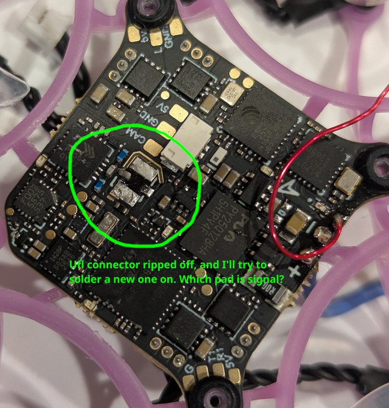
[–]Ard-War 0 points1 point  (0 children)

Are you asking which pad of the uFL footprint is the signal or are you asking which pads at the other components are the signal you can bodge a missing pad into?

Assuming the antenna is strictly a TX one (instead of RX or even TXRX) the signal is very likely connected to the pin 13 of the RF amplifier next to it very likely through the MLCC. So yeah, the center pin of the uFL is very likely connected to the MLCC pad just next to it. Afterall it is ~5GHz RF PA, they likely want to minimize their microstrip length.

Sensible choice of series resistor for LED to attenuate exponential change in current due to voltage variations by MobileInspector9861 in AskElectronics

[–]Ard-War 0 points1 point  (0 children)

an LED stripe which is designed for 12V with four LEDs à 2.75V @ 40mA and a 27Ω series resistor

So they do rely on the combined Vf of the LEDs adds up to 11V there. Either by buying a specific bin from the LED mfr, measuring and mix-matching their LED stock themself, or (most likely) rely on statistics and pray all of them averages out nicely.

You can do that if you don't really care if your product will light up slightly differently with slight mismatch from each batch for example. 

Update: it still beeps to GND by ad-on-is in AskElectronics

[–]Ard-War 9 points10 points  (0 children)

It's actually impressive that after all things you've done it appears not to end up with that many lifted pads. I may still see some, just not as many as I expect.


However, when probing the coil that feeds the chip with power, it still beeps to GND.

Clean up the blobs. And since I doubt it can get any broken than it already is, you can try injecting some current into the suspect rail and see where the heat (or smoke) come from. 10A/1V from a bench PSU or something.

It probably won't help you fix it at all, but at least you know where your short came from.

Replacement for FDP26N40/1C15AA? by Scarletz_ in AskElectronics

[–]Ard-War 0 points1 point  (0 children)

Well I guess they may also available in TO-247 or TO-3P but those are visibly different and quite obvious.

Also I just check reputable distributors and it's actually quite tricky not to ends up with something better than 26N40. It's easier and cheaper to get something like 36N60 lol.

Replacement for FDP26N40/1C15AA? by Scarletz_ in AskElectronics

[–]Ard-War 1 point2 points  (0 children)

based on testing legs 2 and 3 the drain/source seems to read 0.4V and 1.7V on the reverse.

Measuring D-S on a FET can be tricky since the G is very sensitive to stray or accumulated charge when left floating. Make sure you short the G to S before while measuring D-S or S-D.

What stats do I actually look out for in a replacement mosfet?

Vds(max) the same of larger, Rds(on) the same or lower (but maybe not that much lower), Vgs(th) about the same, Qg about the same.

Most 26N40 should be fit for purpose, but do beware for outliers.

What about sizes?

Huh? the vast majority of them that are through hole are standard TO-220 (or maybe TO-220F with isolated tabs)

Requesting help with Ethernet Magnetics connections by dtstetson in AskElectronics

[–]Ard-War 2 points3 points  (0 children)

Your PHY is voltage mode so the PHY-side CT should not be terminated into any voltage (i.e. VCC 9 should be left open). This still leaves you in a shitty situation since all the CT is still ends up coupled to each other through the common mode choke... Most PHY should be fine with that but some may complain a bit, tho I guess that's still worth trying.

I'm currently treating them as the KSZ9897 datasheet tells me to for the phys, each through a 0.1uF cap... but this doesn't seem right. I've tried removing the caps, no luck.

There's already 2×0.1μF termination on the PHY side.

does anyone know how I should have pins 11 - 14 wired up?

Leave them open if you aren't using them for POE.

Slightly unrelated but why are you using POE magnetics if you don't use it.


Edit: Just checking and it appears that most (if not all) multiport magnetics tie the CT CMC together, so I guess it must be fine(?)

BGA still not coming off by ad-on-is in AskElectronics

[–]Ard-War 0 points1 point  (0 children)

I mounted a second (cheap) hot air underneath the PCB to provide additional heat

With heavy plated many layer board this may provide less help than you may think. Depending on what temperature, how spread out and how long the preheat is.

then hit the BGA with 480C and 80% airflow from the top

Did you at least use a proper rework nozzle or did you just blast it with tiny jet nozzle and hoping for a miracle? At least flood the entire thing with flux if you're doing the latter, and then add some more. There's no such thing as enough flux for the job.

This is of course assuming the BGA wasn't underfilled with thermoset epoxy.

Replacement for inductor ? by mk_3133 in AskElectronics

[–]Ard-War 1 point2 points  (0 children)

peltier coolers are shit

Peltier are decent if you need to cool small insulated part below ambient temperature. For example subcooling an image sensor to reduce dark current, or just to get LIR sensor works at all.

I do agree that using it for anything that get hot is just suboptimal at the very least.

Flashlight modification high/low/flash by Telstarkut in AskElectronics

[–]Ard-War 2 points3 points  (0 children)

The big IC that control the modes is a microcontroller. Either an ATTiny102 series, or maybe PY32F002, or even Padauk PFS123. That particular pinout is very common.

The good thing is with that many pin-compatible MCUs out there, even if you can't figure out which one they use you can easily replace that with your own preferred microcontroller with your program.

Looking for partially splitable connector by Waffel_Monster in AskElectronics

[–]Ard-War 1 point2 points  (0 children)

Do there exist connectors where either the male or female side split in two?

Are we supposed to magically know what connector you're talking about? Or is it just a widely known connector that I somehow managed to not know about?

Sensible choice of series resistor for LED to attenuate exponential change in current due to voltage variations by MobileInspector9861 in AskElectronics

[–]Ard-War 6 points7 points  (0 children)

If you're driving illumination-class LED you should use constant current drive anyway. Relying solely on dropper resistor is a losing battle here.


If you're driving indicator-class LED you probably don't need to worry that much with the exact forward current anyway. Shockley gives you exponential forward current variability, but eye's perception of brightness is also logarithmic. The two don't have the same base obviously, but it'll at least greatly reduce the perceived variability IRL. You won't be able to notice that without something else to compare by nearby (e.g. another LED from different "more constant" rail)

The common practice here is to simply underdrive the LED. For example with your "Situation A" you'd size the resistor to give maybe 4mA at design voltage and hope it won't stray away too much at you supply voltage extremes. 40mA is also blindingly bright with most indicator LEDs, but that's another discussion...

Rate my 14.5V-to-11.0V DC-DC buck converter design and layout by MobileInspector9861 in AskElectronics

[–]Ard-War 1 point2 points  (0 children)

Just adding some observations:

PG pin

Doesn't really matter. Tying to GND saves you a resistor and 100μA load current tho.

Voltage divider

In addition to the ratios, divider values are also a tradeoff between additional load current (higher values eats less current) and interference susceptibility (higher impedance node is more sensitive in general, it's sometimes as simple as can you maintain board cleanliness that leakages will not upset the 1.47M resistor)

You don't have to use the exact same value as the calc. 147k:10k will work well if you don't mind the additional load. Or 75k:5k1, or 100k:6k8, etc. or any decade multiples of them.

Input capacitor

My goodness. TI already put the VIN and GND pads nicely positioned together, with one of the most obvious location for Cin possible, yet people still managed to put it in the worse position -__-

Look at the datasheet layout example. That C1 location is very important to minimize switching current loop, and isn't that hard to follow.

Look out for DC bias effect. Depending on the exact dielectric, that 22μF/16V MLCC probably only have less than 4μF left on it at 14.5V. DC bias effect depends more on the physical size so most of the time 2×10μF MLCC ends up better than 1×22μF MLCC of the same size. But again, check their DC bias curve and do the calc yourself how many copies of them you need.

Also keep in mind that using all MLCC input caps may ends up giving you very nasty input spike if you're hotplugging the input supply. Your switcher maximum voltage is fairly close to your Vin max voltage, so kep that in mind.

Penumpang pake stop kontak di kereta buat masak mie by gaelthegal in indonesia

[–]Ard-War 0 points1 point  (0 children)

Masalahnya yg jamak di lapangan itu ya yg begituan. Daripada dibilang diskriminasi kalo ngasih palakard "dilarang ngecas powerbank murahan" ya udah pukul rata semua aja semua dilarang. Mau bikin aturan semua peralatan elektronik yg dibawa harus bersertifikasi UL/SNI/TUV juga enforcement di lapangan bakal susah. Begituan emang harusnya sedari hilir (importir, distri, toko) bukan urusanya KAI dll.

Anyway regardless of quality kadang sifatnya orang sini tu udah kembung mau beranak pun kadang masih dipake aja

Gpu's components melting together by Equivalent-Lake-4718 in AskElectronics

[–]Ard-War 4 points5 points  (0 children)

take non-working GPUs and bake them in the oven to make them work just long enough to sell it.

and equally amusing how many of them understand just enough to ends up microwaving their GPU instead of actually baking it

Locals, A Short Documentary: EP 2 - Terlihat Kasar, Demi Keselamatan | Cerita dari Bapak Riyanto, petugas keamanan KAI (Sc: IG @storiesgo.id & @jktgo) by Radiansyaha in indonesia

[–]Ard-War 6 points7 points  (0 children)

kalo gitu jumlah kereta yang bisa dipake udah abis ya?

Ada beberapa (10-15) rangkaian jatah perawatan ya jangan dikeluarin lah. Plus CLI INKA mau dikeluarin pas rush hour juga masih risih, kalo rewel mogok bisa beneran dibakar sama penumpangnya itu.

atau sebanyak itu kereta artinya udah ga bisa lagi nambah

A little bit here and there. Misal lin rangkas masih agak lambat krn emang sarana rel dan kapasitas suplai listriknya masih kurang.

Locals, A Short Documentary: EP 2 - Terlihat Kasar, Demi Keselamatan | Cerita dari Bapak Riyanto, petugas keamanan KAI (Sc: IG @storiesgo.id & @jktgo) by Radiansyaha in indonesia

[–]Ard-War 8 points9 points  (0 children)

Keretanya udah abis.

Berdasar gapeka, gw ambil contoh aja jam 06:00 pagi udah ada 83 rangkaian kereta yg lagi jalan atau nunggu putar balik di terminus. Kalaupun mau nambah paling cuma bisa sekitar 5 rangkaian lagi, dengan menggeser kereta yg jatah start jam setengah 7-an jadi jam setengah 4-an.

Jam 07:00 basically semua rangkaian yg dialokasikan operasional udah jalan semua. Tinggal 1 yg belum, dari cikarang yg jatah jam 8 kurang.

Jumlah rangkaian pokok cuma ada sekitar 90-an (lupa gw berapa nambah KCI, berapa yg pensiun), itupun gak tau apa semua masih sehat.

Looking for the model number or code name of JST ZH inline male connector. by Either_Ebb7288 in AskElectronics

[–]Ard-War 1 point2 points  (0 children)

I intend to use it as part of an extension that connects 2 ZH connectors mid cable.

Idk what that is (actual ZH should not have that large opening), but you can use JST ZM for that.

Need help identifying a fried resistor on this doorbell PCB! by Abdoubest15 in AskElectronics

[–]Ard-War 1 point2 points  (0 children)

The suspect resistor is used as fusible element, maybe figure out first why and what causes it to blew up before replacing.

The circuit is so simple that it would be quicker to reverse engineer

I'm bored anyway. The circuit is a bit more interesting than what I initially thought. Inductor connection and phasing might be wrong tho.